Friday 2 December 2011

SOLUTION OF EME-102; CENTROID 2


HOW TO FIND THE CENTROID OF A COMPOSITE AREA

(a composite area consists of several straight or curved lines.)

(i) Draw the figure in a coordinate system. Draw the dimensions too. Every dimensions will be measured with respect to origin of the coordinate system


(ii) Divide the composite area into several parts of basic geometric areas. Lebel them as part-1, part-2, part-3, .......part-n. Let the corresponding areas are A1, A2, A3, .... An. Let the centroids are G1(X1,Y1), G2(X2,Y2), G3(X3,Y3), ...... Gn(Xn,Yn).

(iii) Let the centroid of the composite area be G(Xg,Yg). Hence,
Xg = (A1X1 + A2X2 +A3X3)/(A1 + A2 + A3)

Yg = (A1Y1 + A2Y2 +A3Y3)/(A1 + A2 + A3)


(a) Suppose we have certain area of magnitude (A) in a coordinate system. The centroid of the area will be at its mid-point. A centroid is denoted by G.

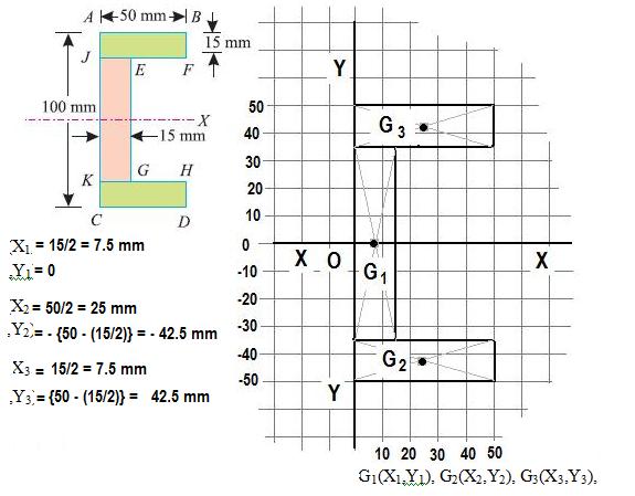
                       In the figure we have a complex geometrical area composed of three basic geometrical areas. Three rectangles. Let us denote the centroids as G1, G2, G3 for the given areas in the figure.

We shall have to find the Centroid of the entire area composed of  A1, A2, A3.

At first, the composite line is divided into three parts.


Part -1 : The middle rectangle : Let the centroid of the area A1 be G1(X1,Y1)

Area, A1 = (100-15-15)x15 mm² = 70x15  mm²  = 1050  mm²                 
          X1 = 7.5 mm
          Y1 =0


Part -2 : The lower Rectangle : Let the centroid of the A2 be G2(X2,Y2)


Area, A2 = 50 x 15  mm² = 750 mm²                
          X2 = 25 mm
          Y2 = - 42.5 mm


Part -3 : The upper Rectangle : Let the centroid of the area Area, A3 be G3(X3,Y3)


Area, A3 = 50 x 15  mm² = 750 mm²                
          X3 = 25 mm
          Y3 = 42.5 mm


If the centroid of the composite line be G  (Xg,Yg)
Xg = (∑AiXi)/(∑Ai


    = (A1X1 + A2X2 +A3X3)/(A1 + A2 + A3)
    = (1050 x 7.5 + 750 x 25 + 750 x 25)/( 1050 + 750 + 750)
    = 17.79 mm
     
Yg = (∑AiYi)/(∑Ai


    = (A1Y1 + A2Y2 +A3Y3)/(A1 + A2 + A3)
    = {1050 x 0 + 750 x (-42.5) + 750 x 42.5}/( 1050 + 750 + 750)
    = 0
As the figure is symmetrical about X axis, hence when we take the line of symmetry as our X axis (as we have taken here), we can directly write, Yg =0

Thursday 1 December 2011

SOLUTION OF EME-102; CENTROID


HOW TO FIND THE CENTROID OF A COMPOSITE AREA

(a composite area consists of several straight or curved lines.)

(i) Draw the figure in a coordinate system. Draw the dimensions too. Every dimensions will be measured with respect to origin of the coordinate system


(ii) Divide the composite area into several parts of basic geometric areas. Lebel them as part-1, part-2, part-3, .......part-n. Let the corresponding areas are A1, A2, A3, .... An. Let the centroids are G1(X1,Y1), G2(X2,Y2), G3(X3,Y3), ...... Gn(Xn,Yn).

(iii) Let the centroid of the composite area be G(Xg,Yg). Hence,
Xg = (A1X1 + A2X2 +A3X3)/(A1 + A2 + A3)

Yg = (A1Y1 + A2Y2 +A3Y3)/(A1 + A2 + A3)


(a) Suppose we have certain area of magnitude (A) in a coordinate system. The centroid of the area will be at its mid-point. A centroid is denoted by G.

                       In the figure we have a complex geometrical area composed of three basic geometrical areas. A rectangle, a semi circle and a isosceles triangle. Let us denote the centroids as G1, G2, G3 for the given areas in the figure.

We shall have to find the Centroid of the entire area composed of  A1, A2, A3.

At first, the composite line is divided into three parts.


Part -1 : The semi-circle : Let the centroid of the area A1 be G1(X1,Y1)

Area, A1 = (π/2)x(25)² mm² = 981.74 mm²                  
          X1 = { 25 -  (4x25)/(3xπ)} mm = 14.39 mm
          Y1 = 25 mm


Part -2 : The Rectangle : Let the centroid of the A2 be G2(X2,Y2)


Area, A2 = 100 x 50  mm² = 5000 mm²             
          X2 = 25 + (100/2) = 75 mm
          Y2 = 25 mm
Part -3 : The Triangle : Let the centroid of the area Area, A3 be G3(X3,Y3)


Area, A3 = (1/2) x 50 x 50 mm² = 1250 mm²             
          X3 = 25 + 50 + 25 = 100 mm
          Y3 = 50 + (50/3) =  66.67 mm


If the centroid of the composite line be G  (Xg,Yg)
Xg = (∑AiXi)/(∑Ai


    = (A1X1 + A2X2 +A3X3)/(A1 + A2 + A3)
    = (981.74 x 14.39 + 5000 x 75 + 1250 x 100)/( 981.74 + 5000 + 1250)
    = 71.09
     
Yg = (∑AiYi)/(∑Ai


    = (A1Y1 + A2Y2 +A3Y3)/(A1 + A2 + A3)
    = (981.74 x 25 + 5000 x 25 + 1250 x 66.67)/ ( 981.74 + 5000 + 1250)
    = 32.20

SOLUTION OF EME-102; EQUILIBRIUM OF FORCES

EQUILIBRIUM OF FORCES IN 2D

A light string ABCDE whose extremity A is fixed, has weights W1 & W2 attached to it at B & C. It passes round a small smooth pulley at D carrying a weight of 300 N at the free end E as shown in figure. If in the equilibrium position, BC is horizontal and AB & CD make 150° and 120° with BC, find (i) Tensions in the strings and (ii) magnitudes of W1 & W2


Although ABCDE is a single string/rope but still the tensions in the string/rope will be different at different segments like in the segment AB the tensions will be T1 , but in BC segment it will be different as the weight is attached at a fixed point (point B) on the string, hence it will be T2 here and in CD it will be T3  there. As at point D the string is not attached rather passes over a smooth pulley hence the tension in DE and CD will be same ie. T3  again.


To solve for equilibrium of forces in 2D, follow these steps:


1. Draw a free body diagram: Draw a diagram of the object in question and identify all the forces acting on it. This will help you visualize the problem and identify any unknown forces or angles.

2. Break forces into components: Resolve all forces into their x- and y-components. This is done by using trigonometry to determine the horizontal and vertical components of each force.

3. Apply Newton's second law: For the object to be in equilibrium, the sum of the forces in the x-direction and the sum of the forces in the y-direction must be equal to zero. This gives you two equations to solve simultaneously.

4. Solve the equations: Solve the equations for the unknown forces or angles by using algebraic methods. This will give you the values of the unknown forces or angles required for the object to be in equilibrium.

5. Check for consistency: Check that the forces and angles you have calculated are consistent with the problem and the free body diagram. For example, make sure that the direction of the forces makes sense and that the angles are reasonable.

6. Interpret the results: Interpret the results and explain what they mean in the context of the problem. This might involve calculating the tension in a rope, the force required to lift an object, or the angle required for an object to remain stationary.


Physics of Inertial Forces

Force Effects Caused by Inertia and Accelerating Reference Frames

Inertial forces are not real forces, rather they are often called as "pseudo forces". They produce effects that feel like forces but actually arise from Newton's inertial law in a reference frame that is accelerating.

When a car accelerates forward rapidly, a person inside the car feel pushed back into their seats. When the car turns around a curve, the person feels pulled to the outside of the curve. If the car suddenly comes to a stop, the persons inside the car not wearing seatbelts fly forward, possibly hitting the windshield. The car’s occupants may feel like some force is pushing them around, but in reality there are no forces shoving them in the directions they move inside the car. They feel shoved around the car because the car is accelerating. The occupants, however, follow Newton’s first law, the inertial law, and continue their original motion, as the car accelerates.


Newton’s First Law

Also called the inertial law, Newton’s first law requires that any object with no outside forces acting on it continues to move at a constant velocity. A constant velocity is a constant speed in a straight line because in physics the velocity includes direction. Any change in an object’s velocity (increasing speed, decreasing speed, or changing direction) is called an acceleration and requires an external force to act on the object. This tendency for objects to continue to move at a constant velocity is called inertia.


Inertial Forces

Despite the name, inertial forces are not real forces. Rather they are effects caused by an object’s inertia when the object is in or on something that is accelerating, what physicists call an accelerating reference frame.

For example, consider the occupants of a car rapidly increasing its speed. They feel pushed back into their seats, but not because some force is shoving them in the chest. The only real force acting on them is the back of the car seat accelerating them forward. Because of Newton’s first law, however, these occupants have inertia that tends to keep them at rest. They feel squeezed back into the car seat because the car is accelerating forward while their inertia would tend to keep them at rest.

When the car goes around a curve, it is also accelerating because the direction of the car’s velocity is changing. The occupants’ inertia tends to keep them moving in a straight line. Hence they feel pulled sideways in the car because they experience an inertial force (or effect) caused by the car’s acceleration as it changes direction.

Flying forward into the windshield when a car stops suddenly (Always wear seatbelts!) is a similar inertial effect. The car accelerates to a stop, and the occupants continue moving forward until their seatbelts (or the windshield) exerts a stopping force on the occupants. There is no real force pushing them forward, they just continue their forward motion, as required by Newton’s first law, while the car accelerates (slowing) to a stop.
Circular Motion

To move in a circular path, an object must have a centripetal force acting on it. The centripetal force points inward towards the center of the circle. The outward centrifugal effect is the tendency of the object to continue in a straight line motion. Hence, the centrifugal effect is an example of an inertial force and is not a real force acting on an object moving in a circular path.

Inertial forces feel like forces, but they are not real forces. They are effects caused by an object’s inertia when it is in or on something that is accelerating.


 D'Alembert's principle of inertial forces

D'Alembert showed that one can transform an accelerating rigid body into an equivalent static system by adding the so-called "inertial force" and "inertial torque" or moment. The inertial force must act through the center of mass and the inertial torque can act anywhere. The system can then be analyzed exactly as a static system subjected to this "inertial force and moment" and the external forces. The advantage is that, in the equivalent static system' one can take moments about any point (not just the center of mass). This often leads to simpler calculations because any force (in turn) can be eliminated from the moment equations by choosing the appropriate point about which to apply the moment equation (sum of moments = zero). Even in the course of Fundamentals of Dynamics and Kinematics of machines, this principle helps in analyzing the forces that act on a link of a mechanism when it is in motion. In textbooks of engineering dynamics this is sometimes referred to as d'Alembert's principle.

d’Alembert’s principle,  alternative form of Newton’s second law of motion, stated by the 18th-century French polymath Jean le Rond d’Alembert. In effect, the principle reduces a problem in dynamics to a problem in statics. The second law states that the force F acting on a body is equal to the product of the mass m and acceleration a of the body, or F = ma; in d’Alembert’s form, the force F plus the negative of the mass m times acceleration a of the body is equal to zero: F - ma = 0. In other words, the body is in equilibrium under the action of the real force F and the fictitious force -ma. The fictitious force is also called an inertial force and a reversed effective force.


Monday 28 November 2011

QUESTION BANKS: Analyse the following Trusses:

 Analyse the following Trusses:

(1)      A cantilever truss has been as shown in the figure. Find the value of W which will produces a force of magnitudes 15 kN  in the member AB.


(2)        A cantilever truss is loaded as shown in the figure. Find the nature and magnitudes of the forces in each link.


(3)      A cantilever truss has been as shown in the figure. Find the value of W which will produces a force of magnitudes 15 kN  in the member AB.


(4)      A truss has been loaded as shown in the figure. Find the nature and the magnitudes of the forces in the links BC, CH and GH by the methods of sections.


(5) A truss has been loaded as shown in the figure. Find the internal forces in each of the beam.


(6)      A truss has been loaded as shown in the figure. Find the forces in each member and tabulate them by any methods.


compiled by Subhankar Karmakar

more content: click the following links for more questions.

THEORETICAL QUESTIONS ON SIMPLE TRUSSES part-3

QUESTION BANK : ENGINEERING MECHANICS PART-2

QUESTION BANK : ENGINEERING MECHANICS


THEORETICAL QUESTIONS ON SIMPLE TRUSSES

SHORT QUESTIONS: TOPIC - TRUSS ANALYSIS

1)      What is a truss? Classify them with proper diagrams.
2)      State the differences between a perfect truss and an imperfect truss.
3)      Distinguish between a deficient truss and a redundant truss.
4)      Write the Maxwell’s Truss Equation.
5)      What are the assumptions made, while finding out the forces in the various members of a truss?
6)      What are the differences between a simply supported truss and a cantilever truss? Discuss the method of finding out reactions in both the cases.


Analyse the following Trusses:
 
(1)      Analyse the Truss by the method of Joints.
(2) Find the internal forces on the links 1, 2 and 3 by the method of Sections.
(3) Determine the magnitude and the nature of the forces in the members BC, GC and GF of the given truss.
(4)   A truss of span 10 m is loaded as shown in the figure. Find the forces in all the links by any method.


compiled by Subhankar Karmakar 

PARALLEL AXIS THEOREM AND IT'S USES IN MOI

Moment Of Inertia of an Area.
MOI or MOMENTS OF INERTIA is a physical quantity which represents the inertia or resistances shown by the body against the tendency to rotate under the action external forces on the body. It is a rotational axis dependent function as its magnitude depends upon our selection of rotational axis. Although for any axis, we can derive the expression for MOI with the help of calculus, but still it is a cumbersome process.


Now suppose we take a different issue. We know MOI of an area about its centroidal axis is easily be obtained by integral calculus, but can we find a general formula by which we can calculate MOI of an area about any axis if we know its CENTROIDAL MOI.

We shall here find that we can indeed derive an expression by which MOI of any area (A) can be calculated about any Axis, if we know its centroidal MOI and the distance of the axis from it's Centroid G.


If IGX be the centroidal moment of inertia of an area (A) about X axis, then we can calculate MOI of the Area about a parallel axis (here X axis passing through the point P) at a distance Ŷ-Y'=Y from the centroid if we know the value of IGX and Y, then IPX will be
IPX = IGX + A.Y2 where Y=Ŷ-Y'


IXX = IOX = IGX + A.Ŷ2
Where IXX is the moment of inertia of the area about the co-ordinate axis parallel to X axis and passing through origin O, hence we can say,

IXX = IOX

 IMPORTANT: The notation of Moment of Inertia

MOI of an area about an axis passing through a point B will be written as IBX


Q: Find the Centroidal Moment of Inertia of the figure given above. Each small division represents 50 mm.

To find out Centroidal MOI