Showing posts with label welding. Show all posts

Wednesday, 4 January 2012

INTRODUCTION TO WELDING PROCESSES


INTRODUCTION TO WELDING PROCESSES

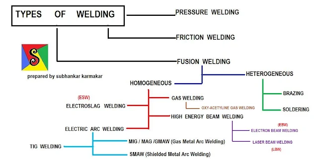
Modern welding technology started just before the end of the 19th century with the development of methods for generating high temperature in localized zones. Welding generally requires a heat source to produce a high temperature zone to melt the material, though it is possible to weld two metal pieces without much increase in temperature. There are different methods and standards adopted and there is still a continuous search for new and improved methods of welding. As the demand for welding new materials and larger thickness components increases, mere gas flame welding which was first known to the welding engineer is no longer satisfactory and improved methods such as Metal Inert Gas welding, Tungsten Inert Gas welding, electron and laser beam welding have been developed. In most welding procedures metal is melted to bridge the parts to be joined so that on solidification of the weld metal the parts become united. The common processes of this type are grouped as fusion welding. Heat must be supplied to cause the melting of the filler metal and the way in which this is achieved is the major point of distinction between the different processes. The method of protecting the hot metal from the attack by the atmosphere and the cleaning or fluxing away of contaminating surface films and oxides provide the second important distinguishing feature. For example, welding can be carried out under a shield comprising of a mixture of metal oxides and silicates which produce a glass-like flux, or the whole weld area may be swept clear of air by a stream of gas such as argon, helium or carbon dioxide which is harmless to the hot metals.

There are certain solid phase joining methods in which there is no melting of the electrodes, though heat is produced in the process. The melted and solidified cast metal is normally weaker than the wrought metal of the same composition. In the solid phase joining such melting does not occur and hence the method can produce joints of high quality. Metals which are dissimilar in nature can also be readily welded by this process. In the normal process joining of dissimilar metals will present problems because of the brittle intermetallic compounds formed during melting. Since the work pieces are closely pressed together, air is excluded during the joining process.

The welding processes those we shall discuss are gas welding, arc welding which includes manual metal arc welding (MMA), tungsten inert gas shielded arc welding (TIG), gas metal arc welding (MIG, MIG/CO2), submerged arc welding (SAW), etc. High energy density processes like electron beam welding, laser beam welding, plasma welding are also dealt with. Pressure welding and some special welding techniques like electro-slag welding etc. are also be discussed in detail.

Gas welding
  • oxygen-acetylene welding
Fusion arc welding
  • Shielded metal arc welding (SMAW)
  • Submerged arc welding (SAW)
  • Flux cored arc welding (FCAW)
  • Gas shielded arc welding (MIG, TIG)
    1. MIG welding (gas metal arc welding)
    2. Pulsed MIG welding
    3. Hot wire MIG
    4. Plasma MIG
    5. TIG welding
    6. Pulsed TIG welding
    7. Hot wire TIG
    8. Spot TIG

Electrical method
  • Electric resistance welding
(a)   spot welding
(b)   seam welding,
(c)    projection welding,
(d)   upset butt welding and
(e)    flash butt welding
  • Electro-slag welding (ESW)
  • Induction pressure welding
Energy method
  • Electron beam welding (EBW)
  • Laser beam welding
  • Plasma welding

Special methods
  • Explosive welding (EW)
  • Friction welding
  • Diffusion bonding

Though the different processes have their own advantages and limitations and are required for special and specific applications, manual metal arc welding continues to enjoy the dominant position in terms of total weld metal deposited. The TIG process produces the finest quality weld on all weldable metals and alloys. The arc temperature may be upto 20,000 K. Although TIG welding produces the highest quality welds, it is a slow and expensive process. Metal inert gas welding process (MIG) is economical with consumable electrode fed at a predetermined rate.

Plasma arc welding (PAW) has made substantial progress in utilising the high heat energy of an ionised gas stream. The jet temperature can be as high as 50,000 K. Foils down to a thickness of 0.01 mm can also be welded in this process and hence this process is more useful in electronic and instrumentation applications.

All the processes like TIG, MIG and PAW can be successfully used for either  Semi-automatic or automatic applications. But they are all open arc processes where radiation and comparatively poor metal recovery put a limit on using high currents. High productivity and good quality welds can be achieved by submerged arc welding process with weld flux and wire continuously fed. The slag provides the shielding of the weld pool with provision for addition of alloying elements whenever necessary.

Electron beam welding and laser welding are classified under high energy density processes.

For efficient welding the power source should provide controlled arc characteristic necessary for a particular job. In one case a forceful deeply penetrating arc may be required, while in another case, a soft less penetrating arc may be necessary to avoid ``burn through''. The welding process will also require a particular type of power source.
 Table 1.1 gives the power source required for widely used welding process.

Tuesday, 3 January 2012

BASIC WELDING TERMS

What is Arc Welding?
Arc welding is a method of joining two pieces of metal into one solid piece. To do this, the heat of an electric arc is concentrated on the edges of two pieces of metal to be joined. The metal melts, while the edges are still molten, additional melted metal is added. This molten mass then cools and solidifies into one solid piece.

Welding Consumables

Stick Electrode A short stick of welding filler metal consisting of a core of bare electrode covered by chemical or metallic materials that provide shielding of the welding arc against the surrounding air. It also completes the electrical circuit, thereby creating the arc. (Also known as SMAW, or Stick Metal Arc Welding.) Basic Welding Terms
MIG Wire
 Like a stick electrode, MIG wire completes the electrical circuit creating the arc, but it is continually fed through a welding gun from a spool or drum. MIG wire is a solid, non-coated wire and receives shielding from a mixture of gases. (Process is also known as GMAW, or Gas Metal Arc Welding.)
Basic Welding Terms
Cored Wire (Flux-Cored Wire)
 Cored wire is similar to MIG wire in that it is spooled filler metal for continuous welding. However, Cored wire is not solid, but contains flux internally (chemical & metallic materials) that provides shielding. Gas is often not required for shielding. (Process is also known as FCAW, or Flux-Cored Arc Welding.)
Basic Welding Terms
Submerged Arc 
A bare metal wire is used in conjunction with a separate flux. Flux is a granular composition of chemical and metallic materials that shields the arc. The actual point of metal fusion, and the arc, is submerged within the flux. (Process is also known as SAW, or Submerged Arc Welding.)
Basic Welding Terms 
Stainless Steel
Stainless steel electrodes and wire are used for welding applications where corrosion resistance is required. Stainless steel consumables are designed to match the composition of stainless steel base metals.
Basic Welding Terms 

Hardfacing
A stick of electrode or cored wire that is designed not to fuse two pieces of metal together, but to add a layer of surface metal to a work-piece in order to reduce wear. An example of this is the shovel on an excavator.
Basic Welding Terms 
Welding Equipment

Stick Welders Heating the coated stick electrode and the base metal with an arc creates fusion of metals. An AC and/or DC electrical current is produced by this machine to create the heat needed. An electrode holder handles stick electrodes and a ground clamp completes the circuit. Basic Welding Terms
TIG Welders 
A less intense current produces a finer, more aesthetically pleasing weld appearance. A tungsten electrode (non-consumable) is used to carry the arc to the workpiece. Filler metals are sometimes supplied with a separate electrode. Gas is used for shielding. (Process is also known as GTAW, or Gas Tungsten Arc Welding.)
Basic Welding Terms
MIG Welders and Multi-Process Welders
Constant Voltage and Constant Current welders are used for MIG welding and are a semi-automated process when used in conjunction with a wire feeder. Wire is fed through a gun to the weld-joint as long as the trigger is depressed. This process is easier to operate than stick welding and provides higher productivity levels. CC/CV welders operate similarily to CC (MIG) welders except that they possess multi-process capabilities - meaning that they are capable of performing flux-cored, stick and even TIG processes as well as MIG.
Basic Welding Terms
Engine Driven Welders
Large stick or multi-process welders are able to operate independent of input power and are powered by a gasoline, diesel, or LPG engine instead. Ideal for construction sites and places where power is unavailable.
Basic Welding Terms
Wire Feeder / Welders
For MIG welding or Flux-Cored wire welding, wire feeder welders are usually complete and portable welding kits. A small built in wire feeder guides wire through the gun to the piece.
Basic Welding Terms
Semiautomatic Wire Feeders
For MIG welding or Flux-Cored welding, semiautomatic wire feeders are connected to a welding power source and are used to feed a spool of wire through the welding gun. Wire is only fed when the trigger is depressed. These units are portable.
Basic Welding Terms
Automatic Wire Feeders
For MIG, Flux-Cored, or submerged arc welding, automatic wire feeders feed a spool of wire at a constant rate to the weld joint. They are usually mounted onto a fixture in a factory/industrial setting and are used in conjunction with a separate power source.
Basic Welding Terms
Magnum Guns / Torches
MIG welding guns and TIG welding torches are hand-held welding application tools connected to both the wire feeder and power source. They direct the welding wire to the weld joint and control the wire feed with the use of a trigger mechanism.
Basic Welding Terms


Cutting

Plasma Cutters
A constricted cutting arc is created by this machine, which easily slices through metals. A high velocity jet of ionized gas removes molten material from the application.
Basic Welding Terms 
Oxyfuel Gas Cutting
Oxyfuel gas cutting process involves preheating the base metal to a bright cherry red, then introducing a stream of cutting oxygen which will ignite and burn the metal.
Basic Welding Terms 

Welding Automation / Robotic Welding
Robotic Welding Systems
The combination of a robotic arm, a welding power source and a wire feeder produces welds automatically using various programs, welding fixtures and accessories.
Basic Welding Terms 
Environmental Systems
Also known as fume extraction, these systems are often incorporated into a robotic fixture to remove welding fumes natural to the process from the welding environment. Usually a vacuum unit, they can be portable or mounted onto a wall.
Basic Welding Terms 

Tuesday, 20 December 2011

WELDING TECHNOLOGY, AN INTRODUCTION

WELDING:

Welding is a fabrication process that joins materials, usually metals or thermoplastics, by melting the workpieces and adding a filler material to it. The workpieces and the filler material are melted to form a pool of molten material (the weld pool) that cools to become a strong joint. To weld metals, although heating is used but sometimes high pressure is also used to fuse the workpieces with filler material.

This is in contrast with soldering and brazing, which involve melting a lower-melting-point material between the workpieces to form a bond between them, without melting the workpieces.

Many different energy sources can be used for welding, including a gas flame, an electric arc, a laser, an electron beam, friction, and ultrasound. While often an industrial process, welding may be performed in many different environments, including open air, under water and in outer space.

Welding is a potentially hazardous undertaking and precautions are required to avoid burns, electric shock, vision damage, inhalation of poisonous gases and fumes, and exposure to intense ultraviolet radiation.


Metallurgy of the Welding Process:

Most solids that are used engineering materials consist of crystalline solids in which the atoms or ions are arranged in a repetitive geometric pattern which is knows as a lattice structure. The only exception is materials that are made from glass which is a combination of a supercooled liquid and polymers which are aggregates of large organic molecules.

Crystalline solids cohesion is obtained by a metallic or chemical bond which is formed between the constituent atoms. Chemical bonds can be grouped into two types consisting of ionic and covalent. To form an ionic bond, either a valence or bonding electron separates from one atom and becomes attached to another atom to form oppositely charged ions. The bonding in the static position is when the ions occupy an equilibrium position where the resulting force between them are zero. When the ions are exerted in tension force, the inter-ionic spacing increases creating an electrostatic attractive force, while a repulsing force under compressive force between the atomic nuclei is dominant.

Covalent bonding is when the constituent atoms lose an electron(s) to form a cluster of ions, resulting in a electron cloud that is shared by the molecule as a whole. In both ionic and covalent boding the location of the ions and electrons are constrained relative to each other, thereby resulting in the bond being characteristically brittle.

Metallic bonding can be classified as a type of covalent bonding for which the constituent atoms of the same type and do not combine with one another to form a chemical bond. Atoms will lose an electron(s) forming an array of positive ions. These electrons are shared by the lattice which makes the electron cluster mobile, as the electrons are free to move as well as the ions. For this, it gives metals their relatively high thermal and electrical conductivity as well as being characteristically ductile.

Three of the most commonly used crystal lattice structures in metals are the body-centred cubic, face-centred cubic and close-packed hexagonal. Ferritic steel has a body-centred cubic structure and austenitic steel, non-ferrous metals like aluminium, copper and nickel have the face-centred cubic structure.

Ductility is an important factor in ensuring the integrity of structures by enabling them to sustain local stress concentrations without fracture. In addition, structures are required to be of an acceptable strength, which is related to a materials yield strength. In general, as the yield strength of a material increases, their is a corresponding reduction in fracture toughness.


Steel Weld Metallurgy

Carbon: Major element in steels, influences strength, toughness and ductility

Manganese: Secondary only to carbon for strength toughness and ductility, secondary de-oxidiser and also acts as a de-sulphuriser.

Silicon: Primary de-oxidizer

Molybdenum: Effects hardenability, and has high creep strength at high temperatures. Steels containing molybdenum are less susceptible to temper brittleness than other alloy steels.

Chromium: Widely used in stainless steels for corrosion resistance, increases hardness and strength but reduces ductility.

Nickel: Used in stainless steels, high resistance to corrosion from acids, increases strength and toughness

Classification of Steel


Steels are classified into groups as follows

  • 1. Low Carbon Steel 0.01 – 0.3% Carbon
  • 2. Medium Carbon Steel 0.3 – 0.6% Carbon
  • 3. High Carbon Steel 0.6 – 1.4% Carbon

Plain carbon steels contain only iron & carbon as main alloying elements, traces of Mn, Si, Al, S & P may also be present.

ALLOY STEEL

Alloy steel is one that contains more than Iron & Carbon as main alloying elements

Alloy steels are divided into 2 groups

  • Low Alloy Steels < 7% extra alloying elements
  • High Alloy Steels > 7% extra alloying elements


Steel Weld Metallurgy

The grain structure of steel will influence its weldability, mechanical properties and in-service performance. The grain structure present in a material is influenced by:

  • The type and number of elements present in the material
  • The temperature reached during welding and or PWHT.
  • The cooling rate after welding and or PWHT

Heat Affected Zone:

The parent material undergoes microstructure changes due to the influence of the welding process. This area, which lies between the fusion boundary and the unaffected parent material, is called the heat affected zone (HAZ). The extent of changes will be dependent upon the following..

  •  Material composition
  •  Cooling rate, fast cooling higher hardness
  •  Heat input, high heat inputs wider HAZ
  •  The HAZ can not be eliminated in a fusion weld

Heat Input Calculation:

Amps = 200 Volts = 32
Travel speed = 240 mm/min
Heat input = (Amps x volts)/(Travel speed mm/sec X 1000)
Heat input = (200 X 32 X 60)/(240 X 1000)
Heat input = 1.6 kJ/mm


Heat Input:

High heat input - slow cooling

  • Low toughness
  • Reduction in yield strength

Low heat input - fast cooling

  •  Increased hardness
  •  Hydrogen entrapment
  •  Lack of fusion

WELDABILITY

Weldability can be defined as the ability of a material to be welded by most of the common welding processes, and retain the properties for which it has been designed.

  •  A steel which can be welded without any real dangerous consequences is said to possess Good Weldability.
  •  A steel which can not be welded without any dangerous consequences occurring is said to possess Poor Weldability. Poor weldability normally generally results in the occurrence of some sort of cracking problem.

Weldability is a function of many inter-related
factors but these may be summarised as:

  •  Composition of parent material
  •  Joint design and size
  •  Process and technique
  •  Access

It is very difficult to asses weldability in absolute terms therefore it is normally assessed in relative terms.

There are many factors which affect weldabilty e.g. material type, welding parameters amps, volts travel speed, heat input.

Other factors affecting weldabilty are welding position and welding techniques.

Basically speaking weldabilty is the ease with which a material or materials can be welded to give an acceptable joint.